aws
(29)
api
(12)
networking
(12)
java
(11)
javafx
(9)
ec2
(6)
javascript
(6)
amplify
(5)
ecs
(5)
react
(5)
website
(5)
appsync
(4)
gamedev
(4)
arduino
(3)
csharp
(3)
docker
(3)
media
(3)
nextjs
(3)
simulation
(3)
unity
(3)
fractal
(2)
rds-database
(2)
cloudwatch
(1)
gitlab
(1)
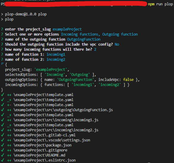
plop
(1)
scaffolding
(1)
serverless
(1)
terraform
(1)
winston-logger
(1)
Arduino-AWS-IoT-Core

Arduino
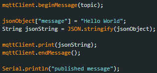
This uses the Arduino MKR WiFi 1010 to publish to AWS IoT over MQTT
Setup
-
Find your AWS Account & Region specific
AWS IoT Broker Endpoint- This can be found here: https://console.aws.amazon.com/iot/home#/settings
-
create the AWS IoT certificate
aws iot create-keys-and-certificate --set-as-active
The Response will be:
{
  "certificateArn": "arn:aws:iot:{Region}:{AccountId}:cert/2c0f72bf-b230-4c49-9e0e-cbf177926d96",
  "certificateId": "2c0f72bf-b230-4c49-9e0e-cbf177926d96",
  "certificatePem": "-----BEGIN CERTIFICATE-----\n{Certificate}\n-----END CERTIFICATE-----\n",
  "keyPair": {
    "PublicKey": "-----BEGIN PUBLIC KEY-----\n{Public Key Material}\n-----END PUBLIC KEY-----\n",
    "PrivateKey": "-----BEGIN RSA PRIVATE KEY-----\n{Private Key Material}\n-----END RSA PRIVATE KEY-----\n"
  }
}
-
Prepare
arduino_secrets.hfile- Enter your Wifi name & password
- Enter your Account & Region specific
AWS IoT Broker Endpointfrom Step 1 - Enter the complete
Device Certificate&Device Private Keyfrom Step 2
-
deploy the
template.yamlincluding thecertificateArnparameter from step 2 -
upload the
.inofile to Arduino using the Arduino IDE -
Published messages will now invoke a Lambda
- Arduino code
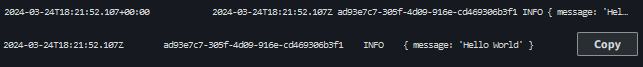
- Cloudwatch Logs
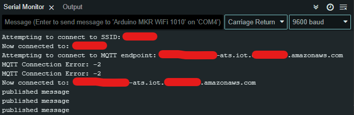
- Arduino code
Arduino Logs
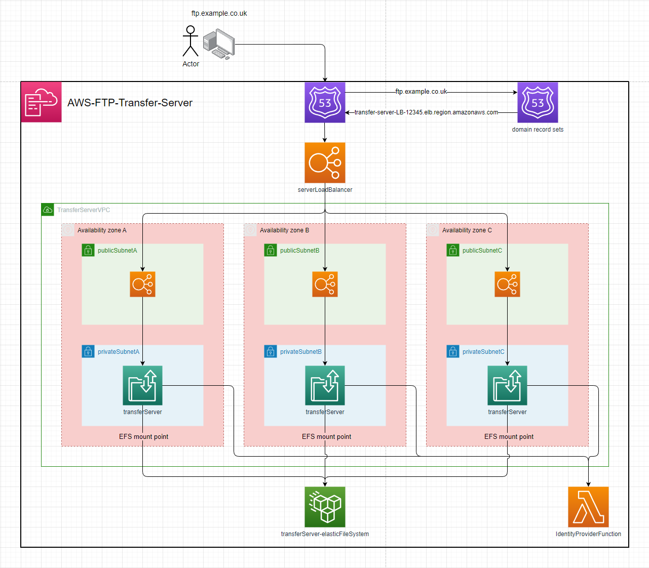
AWS-Transfer-Server
Setup:
- deploy the template to cloudformation
- enter the parameters
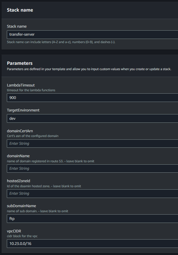
- configuration with a domain:
- including the
hostedZoneId,domainName&domainCertArnparameters will:- Setup the
Certificateon the server & enableFTPSas a protocol - Create a
Route 53 Recordfor thedomainName
- Setup the
- including the
hostedZoneId,subDomainName,domainName&domainCertArnparameters will:- Setup the
Certificateon the server & enableFTPSas a protocol - Create a
Route 53 Recordfor thesubDomainName.domainName
- Setup the
- including the
Usage
The server's url will be output by the stack
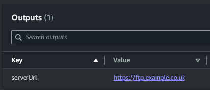
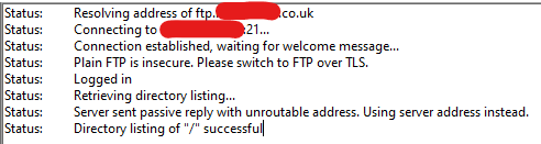
The server can now be connected to over FTP, SFTP & FTPS (if domain is configured)
FileZilla:
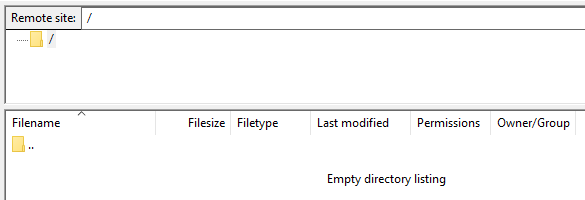
The Identity provider function will be invoked where the payload can be evaludated & integrated into your environment.
{
  "username": "user",
  "sourceIp": "10.23.0.6",
  "protocol": "FTP",
  "serverId": "s-0123456789ABCDEF",
  "password": "password"
}
AVP-auth-api
This API is backed by a Lambda Authorizer that uses Amazon Verified Permissions (AVP) as a cedar policy store and authentication evaluation engine. This can faliciate RBAC & ABAC logic.
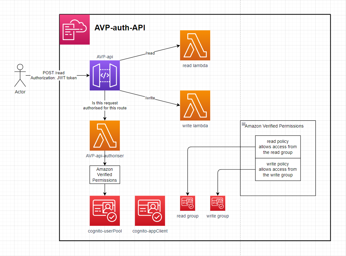
Setup
- Deploy the Application with a given stack name & AVP namespace (used in policy logic)
- Create a user in the deployed Cognito user pool, Add that user to the READ and or WRITE group & log in to the appClient to retrieve a JWT token.
- Make a request to the API url from the stack outputs with the Authorization header as the JWT token.
- If the Cognito user is in the Cognito read group then they'll have access to the /read endpoint. If they've in the write group then they'll have access to the /write endpoint.
The Lost Dungeon 3
Made using Java 16 - Version 16.0.1
Included Libraries:openjfx-16 & com.google.code.gson:gson:1.4
Example room:


Example of the boss room:

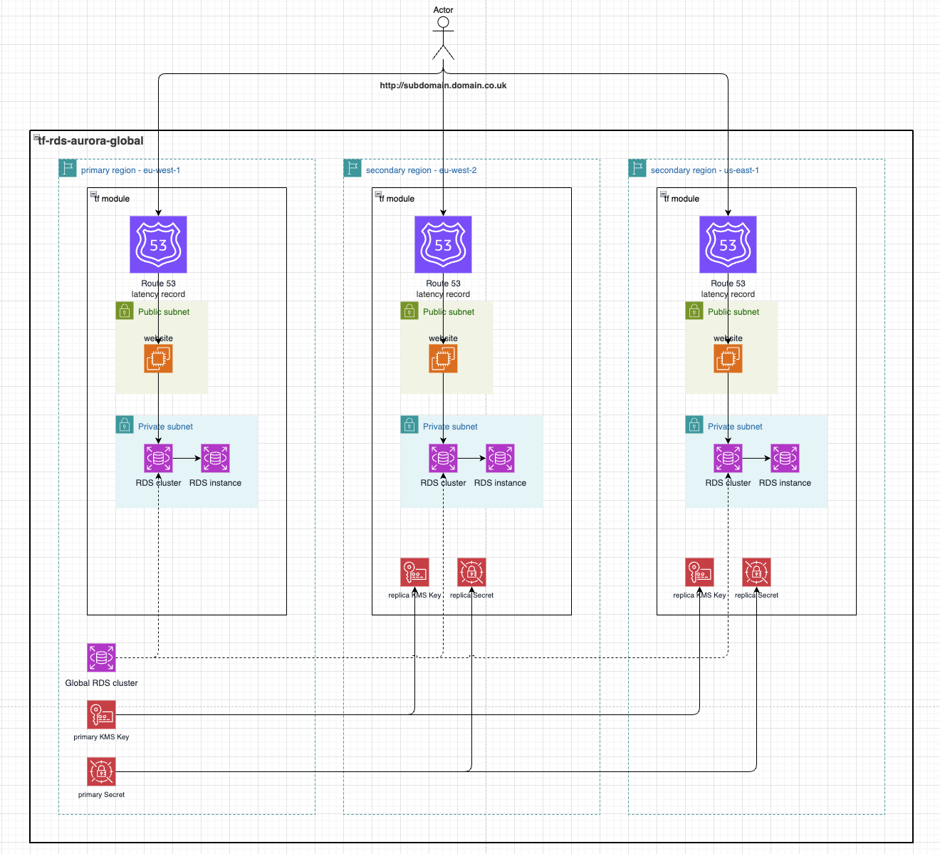
Terraform-Aurora-Global
This demo utilises an AWS RDS Aurora Serverless acting as a global cluster manged by Terraform. It first deploys the primary cluster (the writer) to the specified primaryRegion in variables.tf and it then deploys a cluster (the reader) in each region specified in the secondaryRegions variable in variables.tf. It also generates and configured RDS to authorise with an AWS Secrets Manager Secret which is also replicated to all necessary regions along with the regional KMS Key.
As a simple way to view the data in the RDS database, the application launches a website in a public subnet which queries the app database in RDS to list all users.
Setup
See .gitlab-ci.yml for automated deployment.
-
To initialise Terraform and deploy to AWS it requires an S3 bucket be created to store state. Ensure a bucket is created and initialise Terraform like
terraform init \ -backend-config="bucket=${BUCKET_NAME}" \ -backend-config="key=tf-rds-aurora-global" \ -backend-config="region=${BUCKET_REGION}" -
Configure the desired variables in
variables.tf.- primaryRegion This specifies the primary AWS Region which the writer cluster will be created in. A KMS Key and Secrets Manager Secret will also be created.
- secondaryRegions This is an array of AWS Regions for which a replica reader cluster will be created in. A replica KMS Key and Secrets Manager Secret will also be created.
- domain Optional Route53 domain in the target account. This will cause Route53 Latency records to be created in all specified regions which route to the public EC2 running a website allowing viewing of the users in the
appDatabase. - subDomain Optional subdomain to prefix the domain with when creating the Route53 records.
-
To see what resources Terraform will deploy you can run
terraform planand if that looks ok you can runterraform apply --auto-approvewhich will deploy all resources. -
Once the resources are deployed you'll need to populate the database with some test data before you can view it on the EC2 website.
- Go to AWS Secrets Manager, find the Secret that Terraform created and copy its
Secret ARN - Now go to the AWS console for
Aurora and RDSthenQuery editor. - To connect to the cluster, select it from the dropdown, select
Connect with a Secrets Manager ARNand enter the previously copiedSecret ARNand enter these commands
CREATE DATABASE app;use app; CREATE TABLE users ( id INT PRIMARY KEY, name VARCHAR(100) );use app; INSERT INTO users (id, name) VALUES (1, 'Alice'); INSERT INTO users (id, name) VALUES (2, 'Bob'); - Go to AWS Secrets Manager, find the Secret that Terraform created and copy its
-
Now that's some test data in the DB you can go to the AWS console for
EC2, find thewebsiteInstancethat Terraform created and go to the websitehttp://{Public IPv4 address}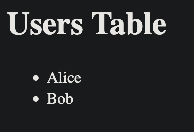
-
There is an equivalent EC2 website created in the regions specified for
primaryRegionandsecondaryRegionswhich query all data created in the users database as the global cluster replicates it across all replica clusters. -
Once done, you can teardown the resources Terraform created with
terraform destroy --auto-approve
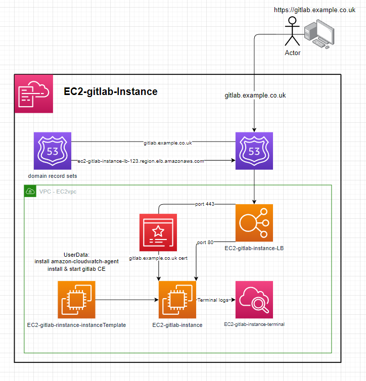
EC2-Gitlab-Instance
Instance:
- ImageId: ami-084e8c05825742534 (eu-west-2)
- InstanceType: t2.medium
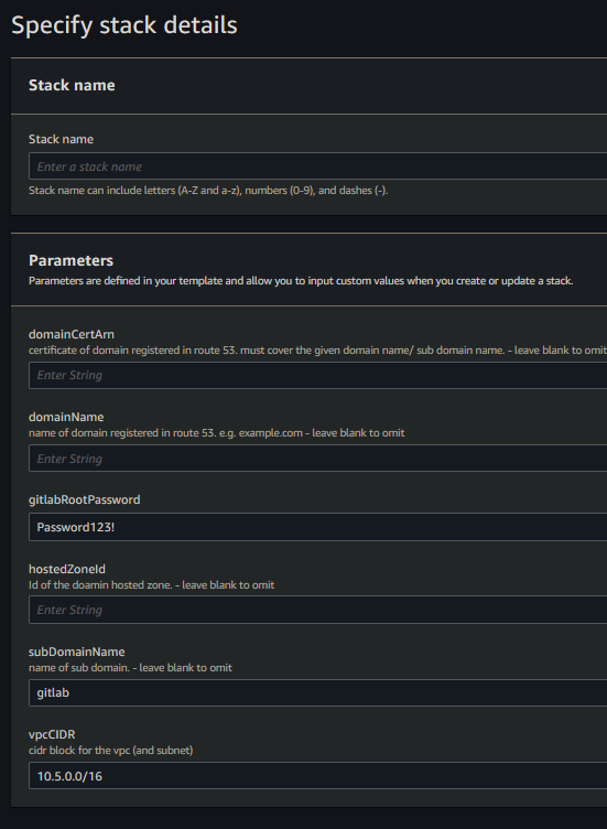
Setup:
- deploy the template to cloudformation
- enter the parameters
- configuration with a domain:
- including the
hostedZoneId,domainName,subDomainName&domainCertArnparameters will:- Create a HTTPS loadbalancer targetGroup & listener with the
domainCertArnon port 443 - Create a dns record in the
hostedZoneIdforsubDomainName.domainNamee.g.gitlab.example.co.uk - Configure the gitlab instance for the domain
subDomainName.domainName
- Create a HTTPS loadbalancer targetGroup & listener with the
- not including the
hostedZoneId,domainName,subDomainName&domainCertArnparameters will:- Omit the HTTPS loadbalancer targetGroup & listener
- Not create any dns records
- Configure the gitlab instance to be accessible from the loadbalancer e.g.
{loadBalancerName}-1234567890.AWS::Region.elb.amazonaws.com
- including the
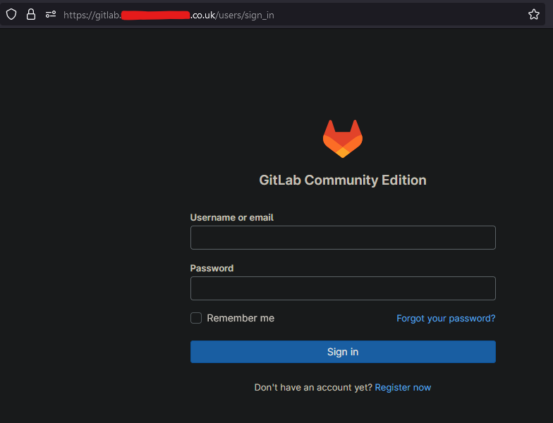
- Give time for the instance to create, it will be accessible from the dns record or the public ELB domain
Notes
Q: Why is a load balancer needed? A: The Gitlab CE installation creates & signs its own HTTPS certificate which some browsers warn about when trying to access the site. The load balancer allows port 443 to be listened on & inject your domain certificate when using HTTPS to resolve this issue.
Q: How do backups work?
A: The gitlab.rb file is configured to send the Gitlab backup, the gitlab.rb file & gitlab-secrets.json. A backup will occur everyday at 00:00. A backup can also be preform by running the preform-backup SSM document.
The default username is root & the userData script sets the password to gitlabRootPassword stack parameter, The default being Password123!
Self-Managed Gitlab CE
Once you finish setting up Gitlab CE you can login, create groups & repos without issue. You can even clone them locally (setup ssh), add files then push them back to your Gitlab. Additionally, You can also register your own runners on a global or group level check this out. These runners can then create resources in aws using a template.yaml & gitlab-ci.yaml.
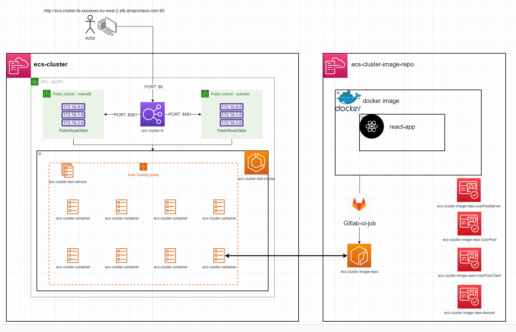
ecs-cluster & ecs-cluster-image-repo are individual repositories / AWS stacks
ecs-cluster
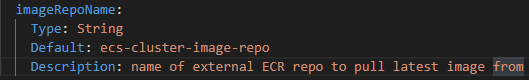
ecs-cluster can be deployed on its own given the imageRepoName parameter is updated to point to an already existing image / ECR repo
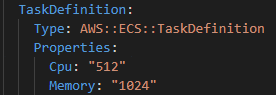
Changing the image might need more resources to be assigned to the Task Defination
Setup
first, deploy ecs-cluster-image-repo to AWS then run the deployDockerImage Gitlab Job to publish the react-app as a docker image to an ECR repository
This job will also run the scripts/envs.sh bash script that appends NEXT_PUBLIC_ to all AWS stack outputs, saves them all to a .env file and compiles it into the docker image for dynamic use of variables inside the image instead of hardcoding values.
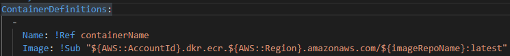
The docker image also exposes port 8081 which the ecs-cluster directs web traffic to.
secondly, deploy ecs-cluster to AWS. The deployment will automatically create an ECS service with a running task. This task can be accessed via the load balancer DNS name that is exported as an output of the ecs-cluster stack. e.g. http://ecs-cluster-lb-12345678.eu-west-2.elb.amazonaws.com/
The ecs-cluster gitlab jobs can also be used to administrate ECS
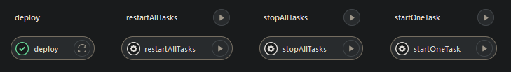
restartAllTasks - gets the number of tasks running e.g. 3 then launches 3 more while shutting down the previous 3. This process will refresh the image in the task if the image has been updated.
stopAllTasks - stops all tasks to save costs
startOneTask - starts 1 task
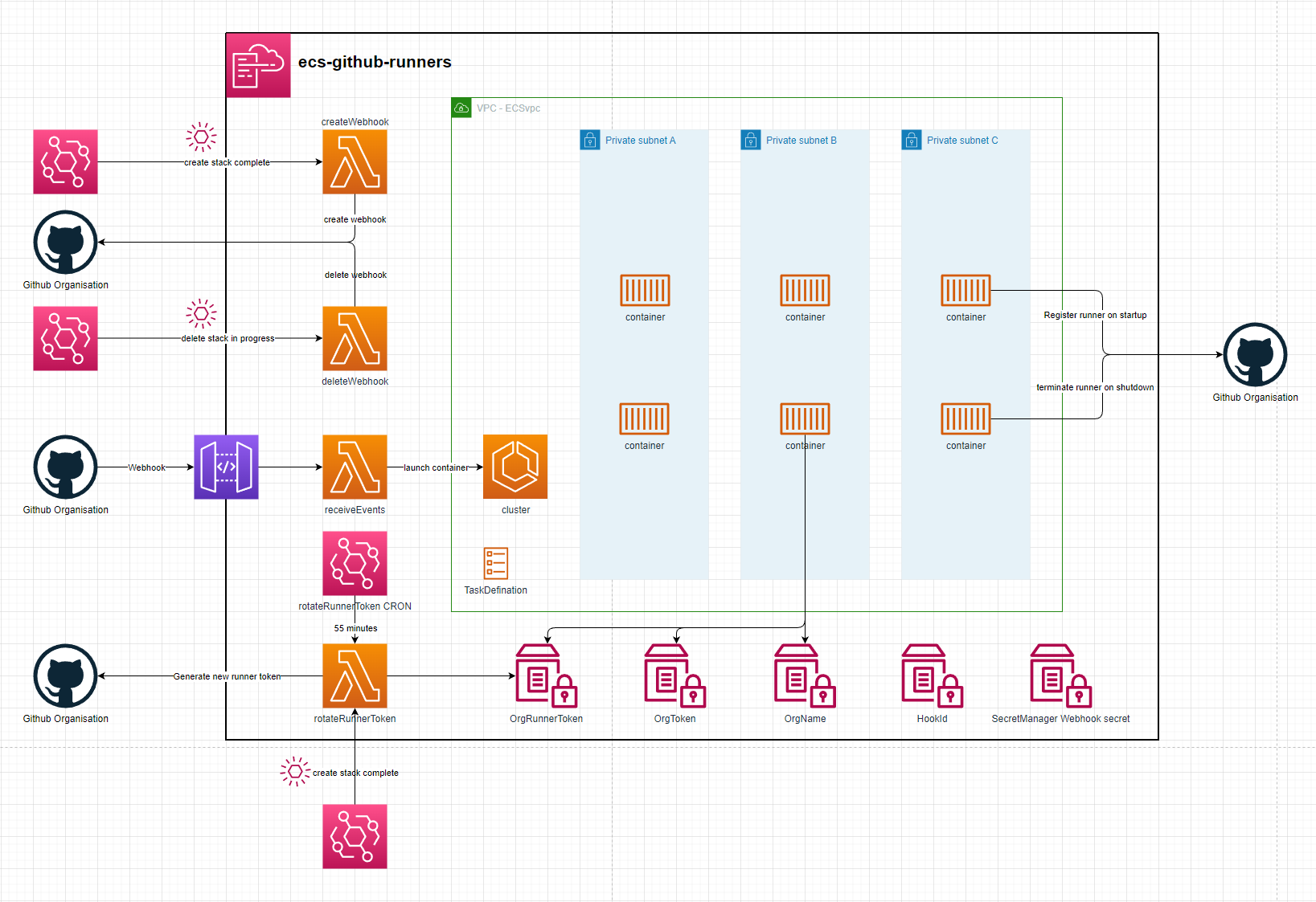
ECS-Github-Runners
setup
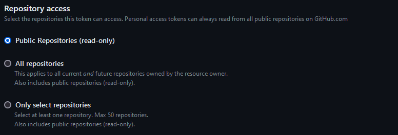
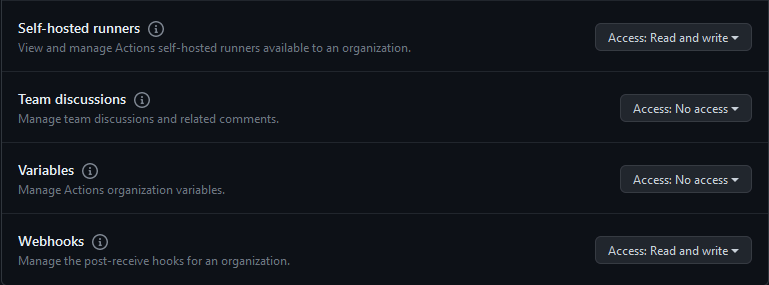
- Generating a Github Org token. An Admin will need to generate an access token allowing access to Webhooks & Self-Hosted Runners
- Deploy the stack using your cli of choice. You will need to specify:
- Your Organisation Name - githubOrgNameParam
- Your Access Token - githubOrgTokenParam
- When the stack finishes creating it will:
- Create a webhook on your organisation - The webhook id will be saved as an SSM Parameter
- Create the initial runner token to be used by the ecs runners. This token only lasts 60 minutes & will be rotated every 55 minutes
- The stack is now ready to receive webhook events. It will scale out an ECS container when it receives a webhook event for a queued workflow and scale it in once the job finishes
ECS Container
The container used by the Github runners is amazonlinux:2023. It then installs a few libraries and registers the github runner to your org. It can take up-tp a minute to install the necessary libraries. Using a custom docker image can minimize start-up times and provide all the libraries commonmly needed for your workflows.
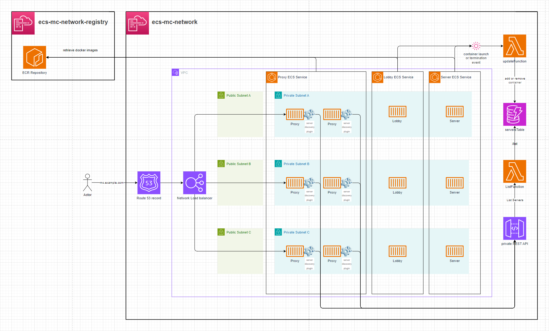
ECS-MC-network
This setup launches x ECS containers, each running a Minecraft server classified as a lobby or a server. All of these servers are accessiable behind an ECS proxy layer allowing players to move between the servers they're connected to.
Setup
See .gitlab-ci.yml for automated deployment.
-
Deploy the
container-registry.yamlCloudFormation stack. -
Build the
Proxy&Serverdocker images to the ECR repository -
Deploy the
template.yamlstack:- Provide the ECR Repositories' ARN via the
ImageUriCloudFormation parameter. - Optionally, configure a domain on the Network Load Balancer in front of the ECS Proxies.
a. Setup without a domain:
- Leave
hostedZoneId,domainName, andsubDomainNameempty. The stack will not create a Route53 record.
b. Setup with a domain:
- Provide values for
hostedZoneId,domainName, andsubDomainName. This will create a Route53 record in front of the Network Load Balancer.
- Provide the ECR Repositories' ARN via the
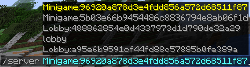
Minecraft Server Proxy
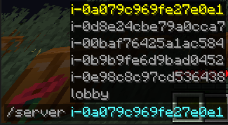
This setup leverages BungeeCord with a custom Java plugin that enables dynamic server discovery, live reloading of proxy target lists, and smooth player session transfers between ECS hosted servers.
This is how the plugin displays the list of proxy targets to the players
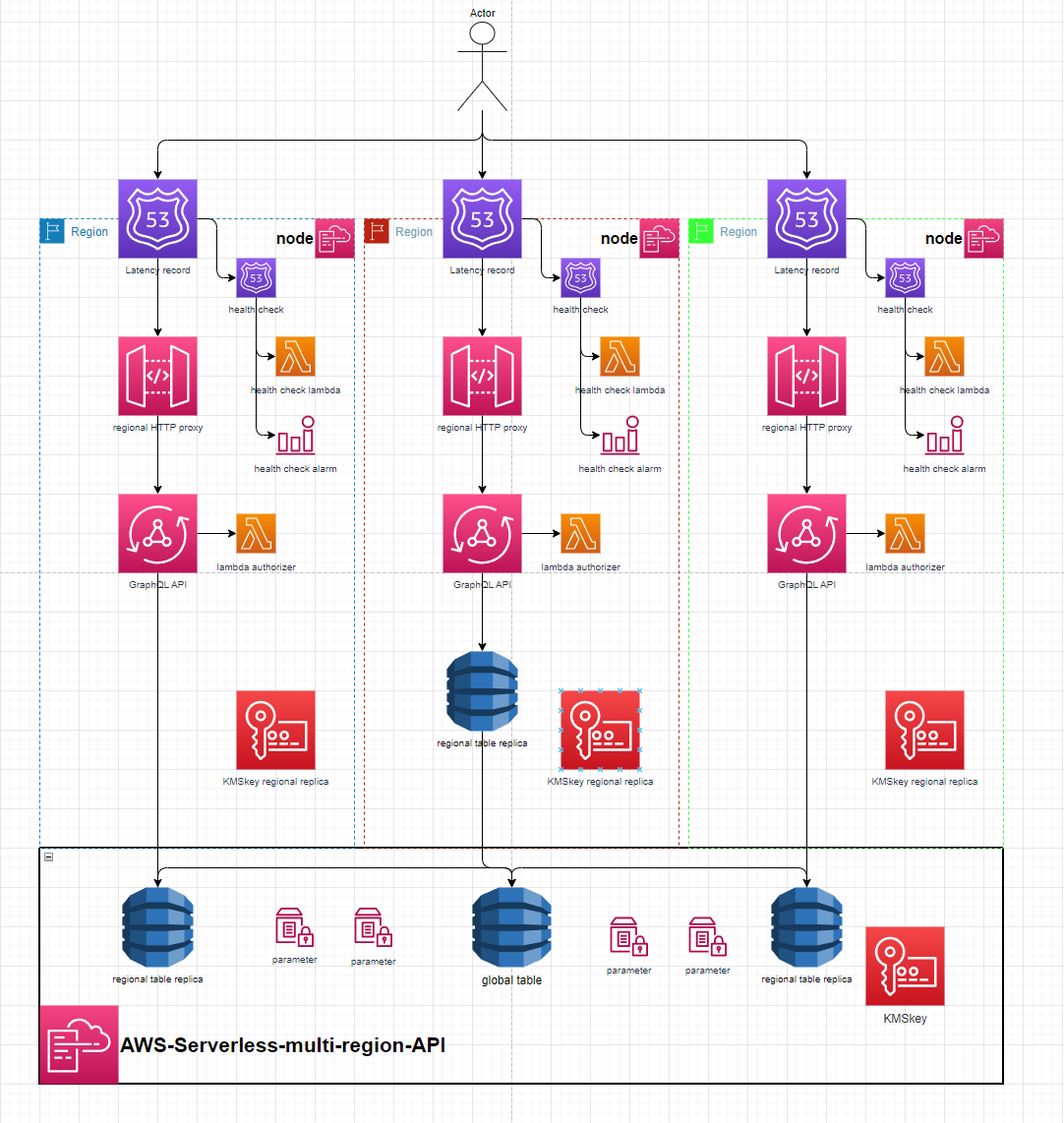
AWS-Serverless-Multi-Region-API
This is a proof of concept global AWS API using the Serverless framwork.
It includes a base api stack made up of a global dynamo table & it's replicas, A KMS key and many SSM parameters to pass relevant Ids & Arns to the node stacks.
The node stacks create a GraphQL API with a HTTP Proxy fronted by a Latency Route53 record with Cloudwatch metric or Lambda health checks for regional failover. The node stacks are designed to be region agnostic and can be deployed into any region that already has a global table replica in. The GraphQL API communicates with the replica in its own region to provide the lowest possible latency to access data across the globe.
The base api stack also includes a KMS key that's replicated in each node stack. The intention of this was to be used by the Lambda Authorizer for the region specific GraphQL API to authorize encrypted credentials stored in the global table as a 'global' authentication mechanism. This was preferable compared to AWS managed regional API keys (would fail if requests were routed to the region that the key wasn't created in) or cognito authorization which are inherently non-global
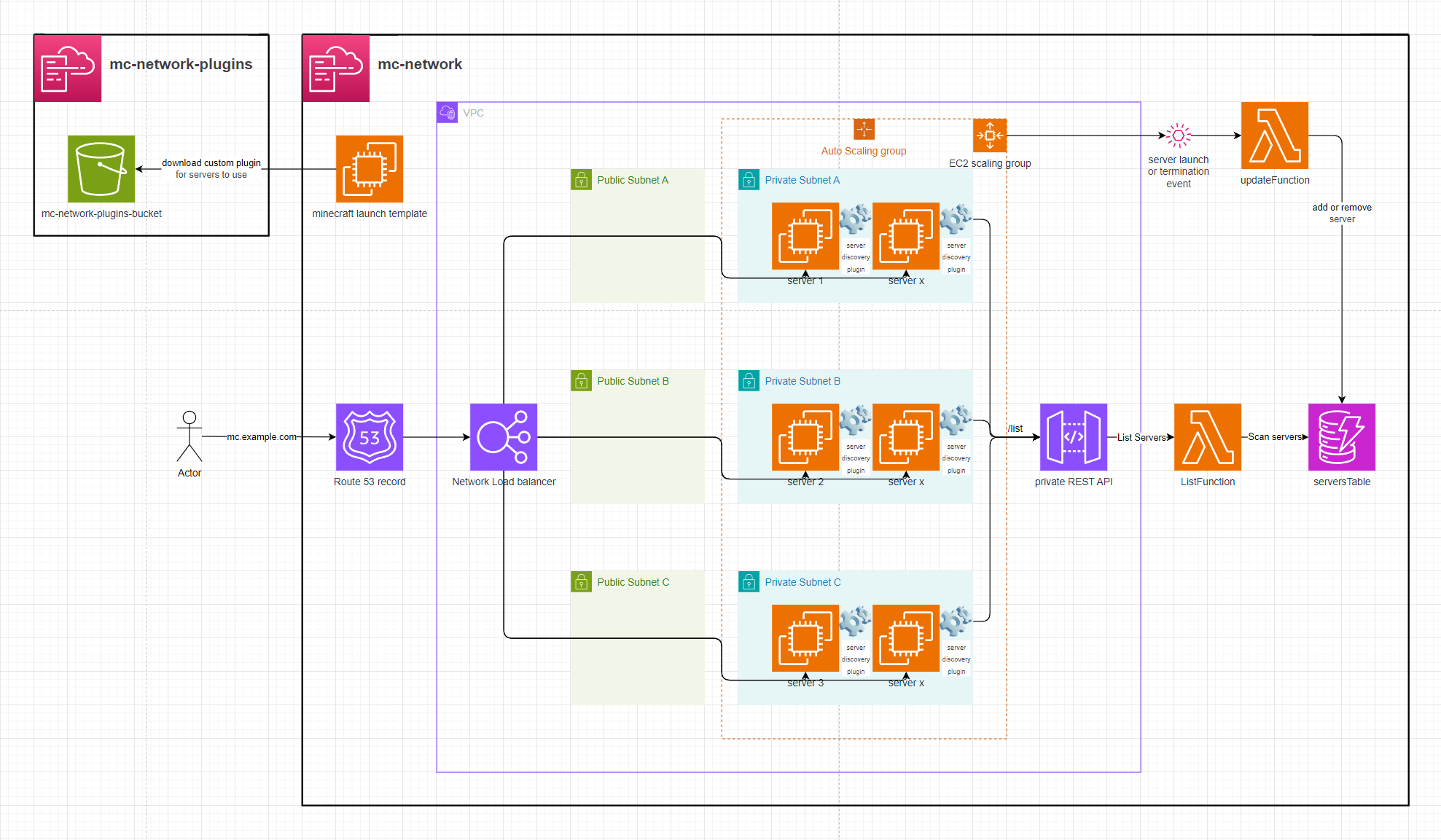
AWS-EC2-minecraft-server-mesh
This setup launches x EC2 instances, each running a Minecraft server. A custom Bungee plugin connects all the servers, forming a mesh network that allows players to move between them seamlessly using the /server <EC2 instance name> command in Minecraft chat.
Setup
See .gitlab-ci.yml for automated deployment.
-
Deploy the
plugin-template.yamlCloudFormation stack. -
Build the
BungeeServerListBungee plugin and upload it to the stack's S3 bucket:- Package the plugin using
mvn, e.g.mvn clean package - Upload the resulting JAR file (in
target/) to the S3 bucket created by the stack.
- Package the plugin using
-
Deploy the
template.yamlstack:- Provide the plugin's S3 path via the
pluginDirectoryCloudFormation parameter. - Configure the number of EC2 instances via the
scalingGroupDesiredSizeparameter. - Optionally, configure a domain on the Network Load Balancer in front of the Minecraft server mesh.
a. Setup without a domain:
- Leave
hostedZoneId,domainName, andsubDomainNameempty. The stack will not create a Route53 record.
b. Setup with a domain:
- Provide values for
hostedZoneId,domainName, andsubDomainName. This will create a Route53 record in front of the Network Load Balancer.
- Provide the plugin's S3 path via the
Minecraft Server Proxy
This setup leverages BungeeCord with a custom Java plugin that enables dynamic server discovery, live reloading of proxy target lists, and smooth player session transfers between servers in the mesh.
This is how the plugin displays the list of proxy targets to the players
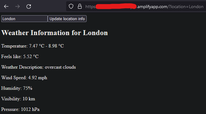
AWS-Amplify-Weather-App
uses the openweathermap api to retrieve data
Setup
- deploy weather-app-2-frontend to gitlab, make note of its project_id
- create an access token that allows
READ REPOaccess to the frontend - this will be used by Amplify - get an api access token from openweathermap
- deploy backend & setup with CICD variables
FRONTEND_REPO_PROJECT_ID,AMPLIFY_TOKEN&WEATHER_API_TOKEN - run the
update-frontendCICD job on either repo to have Amplify get the most recent frontend commit on the specified branch & deploy it to the backend - check the Amplify website


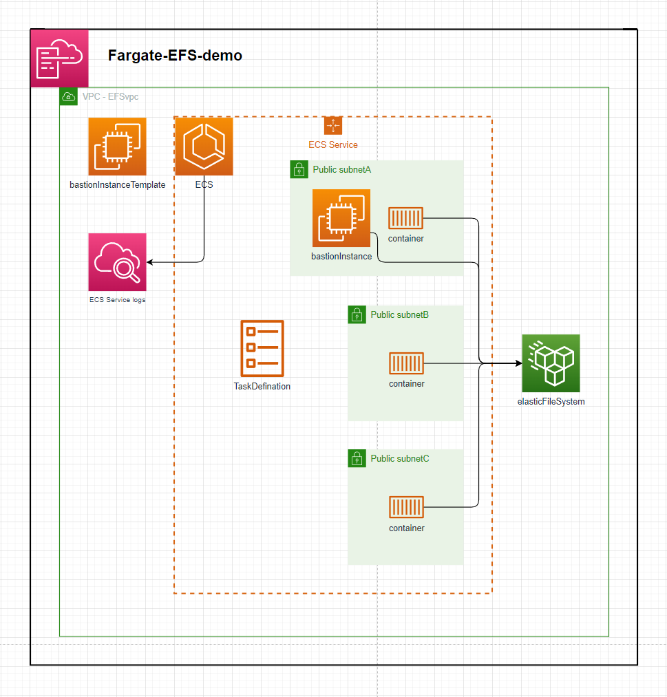
Fargate-EFS-demo
The template in this repository defines an ECS Service that launches containers backed by an Elastic File Ssytem as a mounted volume
Setup:
- deploy the template - speficy stack parameters
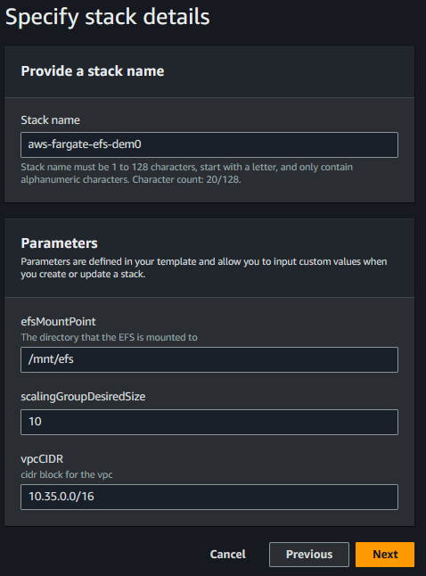
- By default this will create a VPC with the default CIDR parameter. The ECS Service will launch 10 instances in the VPC across 3 AZs. Each subnet mounts to the Elastic File System and each container mounts to the
efsMountPointdirectory & touchs a file into that directory. - The EC2 bastion instance can be connected to view the mounted directory. E.g. An ECS Service of 10 containers will individually create 1 file each in the mounted directory.
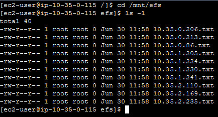
Example:
ECS Service with 10 Tasks
Each Task's container will create a file in the efsMountPoint directory
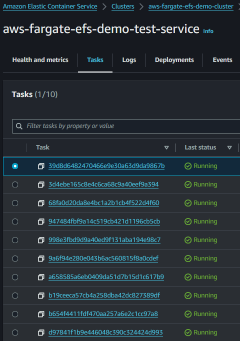
You can connect to the bastion instance to check the files in the mounted directory
AWS-Asynchronous-api
Implementation of an asynchronous AWS API using SQS to buffer & batch requests with dynamo as a central store for the events, their status and their result. The processFileFunction artificially pauses for 2 - 8 seconds to simulate processing with message.
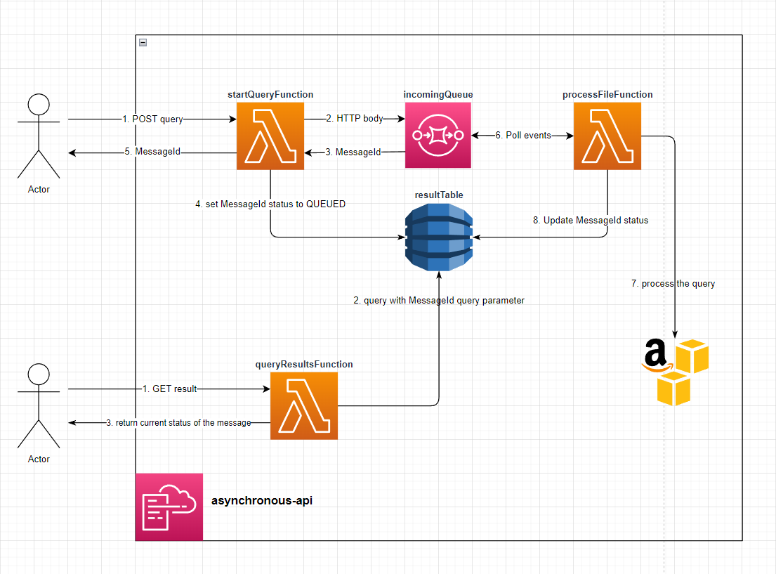
setup
Deploy the Stack - The API url will be Output from the stack.
Make a POST request to: the /StartQuery endpoint with any body (it doens't validate the body) - You will recieve a response body like:
{
  "MessageId": "4b39d05e-1add-40fe-8c77-6255e5700522",
  "Status": "QUEUED"
}
Make a GET request to the /QueryResults endpoint with the MessageId query parameter - If the message is still in the QUEUED status then you will recieve:
{
  "MessageId": "4b39d05e-1add-40fe-8c77-6255e5700522",
  "Status": "QUEUED"
}
If The message is in the FINISHED status you will recieve
{
  "ttl": "1689212154",
  "Status": "FINISHED",
  "MessageId": "4b39d05e-1add-40fe-8c77-6255e5700522"
}
Arduino-AWS-IoT-Core
Arduino
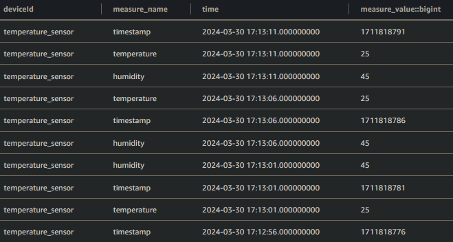
This uses the Arduino MKR WiFi 1010 to publish Temperature & Humidity sensor data to AWS Timestream through AWS IoT Core using MQTT

Setup
-
Find your AWS Account & Region specific
AWS IoT Broker Endpoint- This can be found here: https://console.aws.amazon.com/iot/home#/settings -
create the AWS IoT certificate
aws iot create-keys-and-certificate --set-as-active
The Response will be:
{
  "certificateArn": "arn:aws:iot:{Region}:{AccountId}:cert/2c0f72bf-b230-4c49-9e0e-cbf177926d96",
  "certificateId": "2c0f72bf-b230-4c49-9e0e-cbf177926d96",
  "certificatePem": "-----BEGIN CERTIFICATE-----\n{Certificate}\n-----END CERTIFICATE-----\n",
  "keyPair": {
    "PublicKey": "-----BEGIN PUBLIC KEY-----\n{Public Key Material}\n-----END PUBLIC KEY-----\n",
    "PrivateKey": "-----BEGIN RSA PRIVATE KEY-----\n{Private Key Material}\n-----END RSA PRIVATE KEY-----\n"
  }
}
-
Prepare
arduino_secrets.hfile- Enter your Wifi name & password
- Enter your Account & Region specific
AWS IoT Broker Endpointfrom Step 1 - Enter a unique identifier for the device.
- Enter the complete
Device Certificate&Device Private Keyfrom Step 2
-
deploy the
template.yamlincluding thecertificateArnparameter from step 2. The template will listen on a topic with the same name as the stack. -
upload the
.inofile to Arduino using the Arduino IDE -
The board will now publish the Temperature & Humidity data from the
DHT22sensor and publish it to Timestream throughAWS IoT Core
Arduino Logs
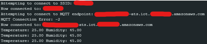
Timestream Example
Secure Media Streaming
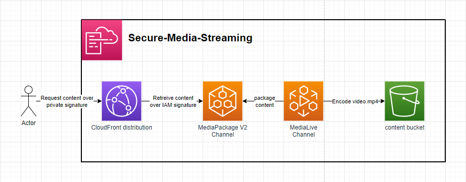
The template defines a secure method of streaming content over HLS utilising AWS CloudFront, AWS MediaPackage V2 & AWS MediaLive. The clients make a RSA signed request to CloudFront which signs the request using AWS sigv4 & forwards the request to the MediaPackage V2 Origin Endpoint - This ensures clients can only request the content from CloudFront in a more controlled manner.
Setup:
- generate a public-private key pair. E.g.
openssl genrsa -out private_key.pem 2048; openssl rsa -pubout -in private_key.pem -out public_key.pem. This will generate aprivate_key.pem&public_key.pem. - Deploy the template including the in-line
public_key.pemfor theAWS::CloudFront::PublicKeyresource. - Add an exmpale video file called
video.mp4to theContentBucket. - Starting the MediaLive Channel will now start transcoding the packaging the
video.mp4to be consumed over HLS - Signed requests using the
private_key.pemcan now be made to the Cloudfront Domain to securely retreive HLS content - Signed requests can be generted using the included
signer.jswhen providing thekeyPairIdandcloudfrontDomainafter deploying the stack
Setup
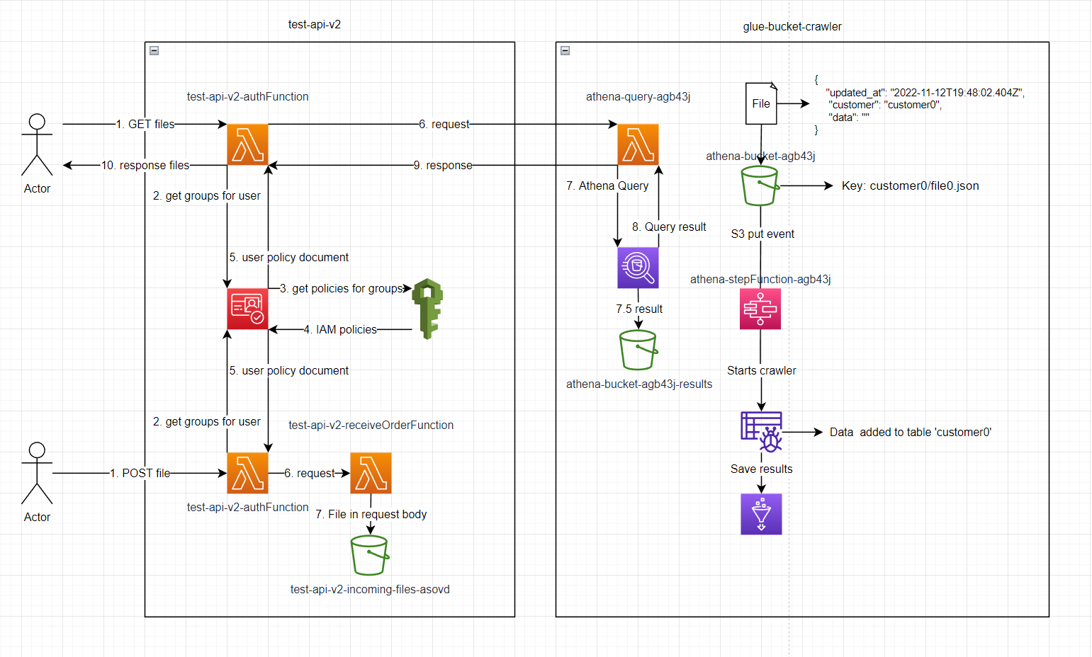
deploy glue-bucket-crawler, wait for it to be finished then deploy test-api-v2
execute lambda test-api-v2-create-user with event:
{ "Username": "customer0", "Password": "Password123!", "Email": "a@b.com" }
go to the user in cognito, add them to the group test-api-v2-UserPoolClient-FileGroup
add file to S3 bucket athena-bucket-agb43j/customer0/file.json
Make a GET request to the /File endpoint with the Authorization: Basic Y3VzdG9tZXIwOlBhc3N3b3JkMTIzIQ==
All elements of the json file will be returned.
supporrted query parameters: token, updated_at, limit & page
File must contain updated_at timestamp e.g. 2022-11-12T19:48:02.404Z to use the updated_at query parameter.
AWS Webcoket API
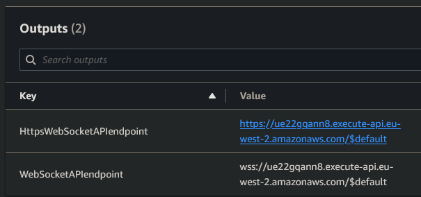
This template.yaml defines a Websocket API that uses dynamo to store active connectionIds and push updates downstream to connections

Setup:
- Deploy repository to AWS
- Get
WebSocketAPIendpointfrom the stack outputs - E.g.wss://ue22gqann8.execute-api.eu-west-2.amazonaws.com/$default
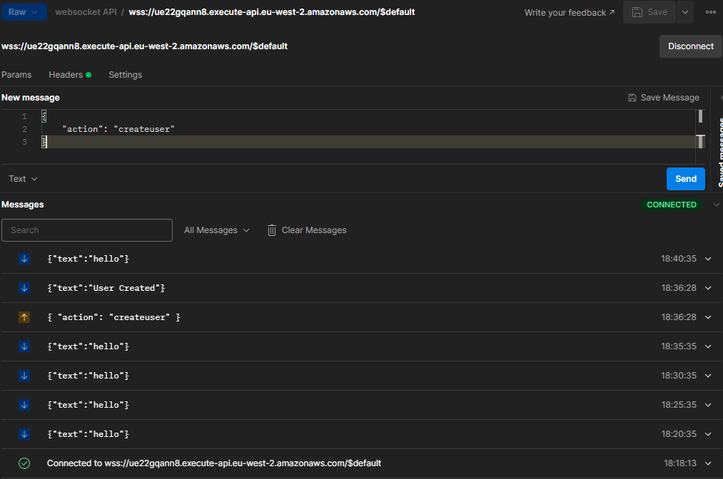
Usage
- Connect to
WebSocketAPIendpoint- Every 5 mins the
connectionUpdaterFunctionwill run and push a message to all active connections. - Send a configured action to the API such as
- Every 5 mins the
{
    "action": "createuser"
}
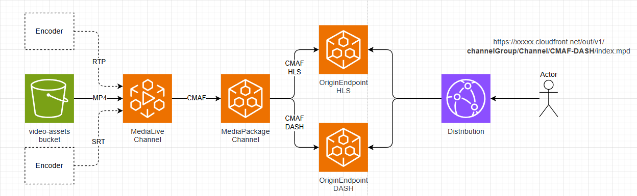
AWS Media Pipeline
This application defines an AWS media processing pipeline using AWS MediaLive to encode an input MP4 file. The resulting CMAF segments are sent to AWS MediaPackage V2, where they are packaged as HLS and DASH for playback by clients through a CloudFront distribution.
Prerequisites
- Create an S3 bucket in the target region you intend to deploy to, and upload an MP4 file.
- Copy the S3 URI of this object for use during setup.
Setup
See .gitlab-ci.yml for automated deployment.
- Use AWS SAM or your preferred method to deploy the CloudFormation template to AWS.
- Set the
S3Pathstack parameter to the path of your MP4 file in S3, for example:
s3://<bucket>/<file>.mp4
- Set the
- Go to the AWS MediaLive console and turn on the channel that was deployed.
- Go to the Outputs of the deployed CloudFormation stack. Review:
- The packaged HLS stream via the
hlsPreviewLinkoutput. - The packaged DASH stream via the
dashPreviewLinkoutput.
- The packaged HLS stream via the
- Finally, turn off the MediaLive channel.
wave-function-collapse
Initial testing:

The small boxes are representing a blank tile


tests with more complicated tile sheets after adding dynamic rules

addition of asymmetric tiles

proof of concept dungeon layout
could be used for The-Lost-Dungeon-4?

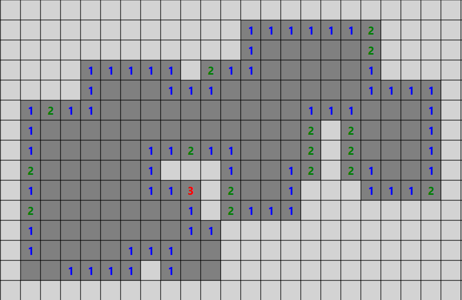
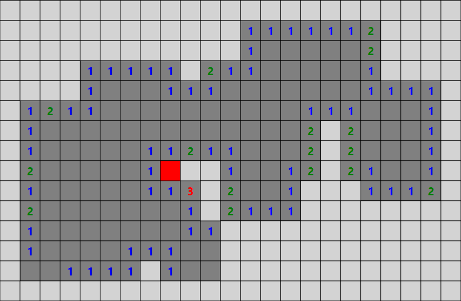
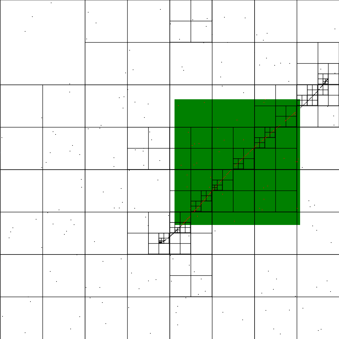
A-Star Path Finding Algorithm
Implementation of A-Star Path Finding Algorithm
setup
- Run the code
- Left click = start square
- right click = finishing square
result


Green - Start point
Red - End point
Dark-Blue - options that have been evaluation
Light-Blue - options that are next to be evaluated
Purple - The shortest path to the end

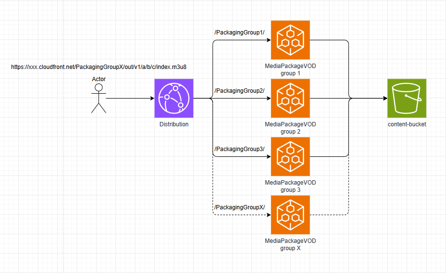
CloudFront MediaPackage VOD Asset Sharding
This application shows an approach to spread a large number of MediaPackage VOD Assets across different MediaPackage Packaging Groups using CloudFront cache behaviors to route requests to the correct origin that matches the Packaging Group name in the asset URL path parameters. This is an effective approach to avoid the AWS quotas & performance drawbacks of storing a large number of assets in one Packaging Group.
Setup
See .gitlab-ci.yml for automated deployment.
- Use AWS SAM or any preferred method to deploy the CloudFormation template to AWS.
- Upload any valid HLS, DASH, etc. media to the bucket defined in the CloudFormation template.
- Ingest that asset into AWS MediaPackage VOD, specifying one of the Packaging Groups defined in the CloudFormation template.
- Once the asset is packaged, you will get a URL like
https://xxx.egress.mediapackage-vod.us-east-1.amazonaws.com/out/v1/a/b/c/index. - Replace the MediaPackage VOD domain with the CloudFront domain and make the chosen Packaging Group name the first URL path parameter, like:
https://xxx.cloudfront.net/PackagingGroupX/out/v1/a/b/c/index - Making a request to this URL will have CloudFront's cache behavior match the path parameter to the correct origin and direct it to MediaPackage VOD.
cloudwatch-winston-logger
Example
const { Logger } = require('./utils/winstonLogger');

let logger = new Logger(context, { metadata0: 'xyz' });

let metadata1 = "abc";
let metadata2 = "def";
let metadata3 = "ghi";
logger.info(event);
logger.addMetadata({ metadata1 });
logger.info(event);
logger.addMetadata({ metadata2 },  { metadata3 });
logger.warn(event);
logger.removeMetadata('metadata1');
logger.http(event);
logger.removeMetadata('metadata2',  'metadata3');
logger.report(event);
Output
{"level":"info", "message":{"key":"value"}, "metadata0":"xyz"}
{"level":"info", "message":{"key":"value"}, "metadata0":"xyz", "metadata1":"abc"}
{"level":"warn", "message":{"key":"value"}, "metadata0":"xyz", "metadata1":"abc", "metadata2":"def", "metadata3":"ghi"}
{"level":"http", "message":{"key":"value"}, "metadata0":"xyz", "metadata2":"def", "metadata3":"ghi"}
{"level":"report", "message":{"key":"value"}, "metadata0":"xyz"}
Example
  try {
    await Promise.all(jobs);
  } catch (err) {
    logger.error(new Error(err));
  }
Cloudwatch Output
{
    "awsRequestId": "b04c613a-64e5-4fb6-b2c0-5085f971ded6",
    "level": "error",
    "message": "ReferenceError: jobs is not defined",
    "stack": [
        "Error: ReferenceError: jobs is not defined",
        "    at Runtime.handler (/var/task/src/index.js:34:18)",
        "    at Runtime.handleOnceNonStreaming (file:///var/runtime/index.mjs:1089:29)"
    ]
}


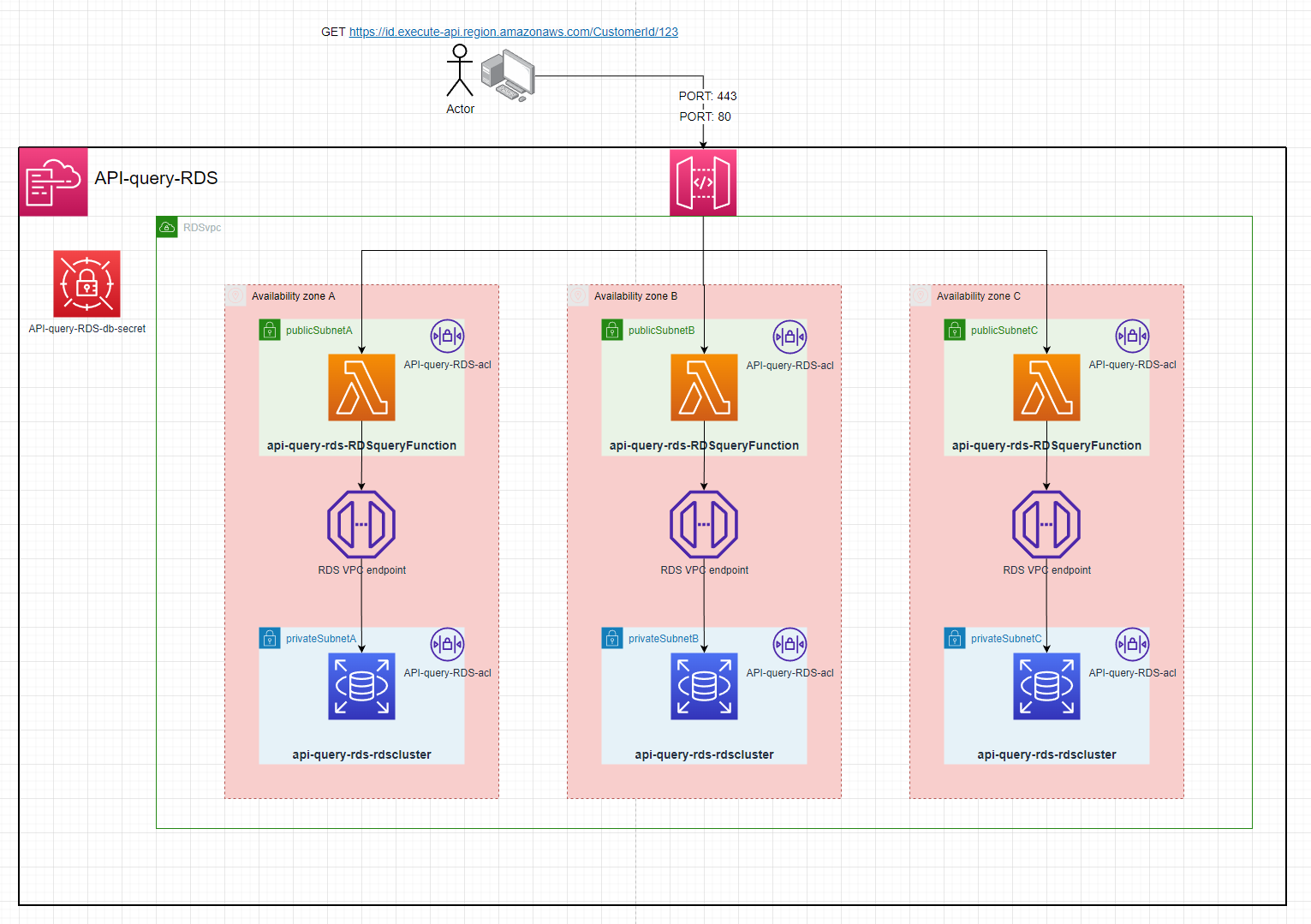
API-query-RDS
Setup:
- Deploy project to aws
- Copy the
RDSDBSecretArnoutput by the stack - Go to RDS & select
Queryon the database - enter these credentials with the
Secrets manager ARNas theRDSDBSecretArn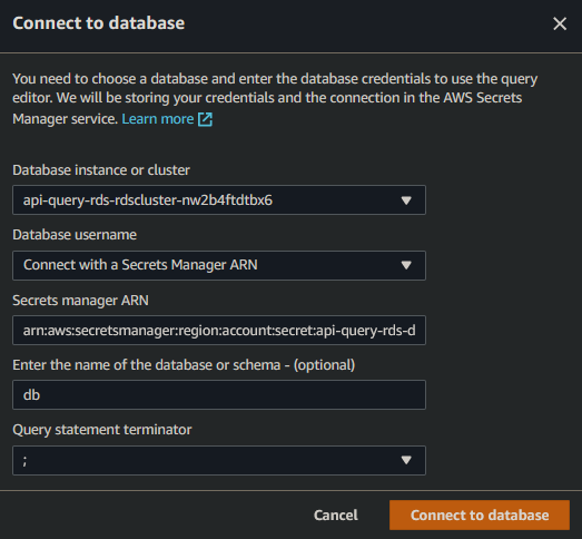
- create the
CustomersTable
CREATE TABLE Customers (
  CustomerId int,
  FirstName varchar(255)
)
- create a few example customers
INSERT INTO Customers (CustomerId, FirstName) VALUES (100, 'Name');
INSERT INTO Customers (CustomerId, FirstName) VALUES (101, 'Name1');
INSERT INTO Customers (CustomerId, FirstName) VALUES (102, 'Name2');
- make a
GETrequest to theHttpApiUrloutput by the stack. Making a GET request tohttps://ID.execute-api.region.amazonaws.com/CustomerId/100. You will recieve:
[
    {
        "CustomerId": 100,
        "FirstName": "Name"
    }
]
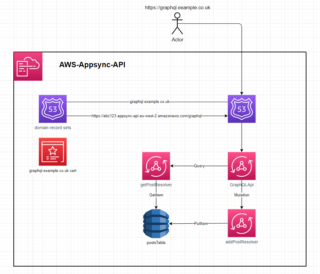
Appsync GraphQl API
This template.yaml defines an AppSync API that uses dynamo resolvers to directly interface with a dynamo table
Setup:
- deploy the template - speficy stack parameters
- setup without a domain
- leave the
domainCertArn,domainName,hostedZoneId&subDomainNameblank. The stack outputs will be theAPI url& anAPI token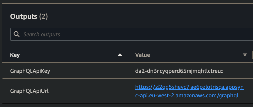
- leave the
- setup with a domain
- enter a value for
domainCertArn,domainName&hostedZoneId. This will create an Appsync domain association and a route53 record
- enter a value for
- setup with a domain and subdomain
- enter a value for
domainCertArn,domainName,hostedZoneId&subDomainName. This will create an Appsync domain association and a route53 record forsubDomainName.domainName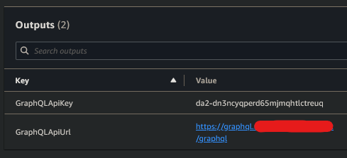
- enter a value for
- setup without a domain
Usage
creating a post
mutation addPost {
  addPost(
    author: "AUTHORNAME"
    title: "Our first post!"
    content: "This is our first post."
    url: "https://aws.amazon.com/appsync/"
  ) {
    id
    author
    title
    content
    url
  }
}
This mutation will return:
{
    "data": {
        "addPost": {
            "id": "8b909b4c-77c0-4aab-a44f-34e7fd7e04b7",
            "author": "AUTHORNAME",
            "title": "Our first post!",
            "content": "This is our first post.",
            "url": "https://aws.amazon.com/appsync/"
        }
    }
}
This id can be used with the getPost Query
getting a post
query getPost {
  getPost(id: "8b909b4c-77c0-4aab-a44f-34e7fd7e04b7") {
    id
    author
    title
    content
    url
  }
}
This query will return:
{
    "data": {
        "getPost": {
            "id": "8b909b4c-77c0-4aab-a44f-34e7fd7e04b7",
            "author": "AUTHORNAME",
            "title": "Our first post!",
            "content": "This is our first post.",
            "url": "https://aws.amazon.com/appsync/"
        }
    }
}
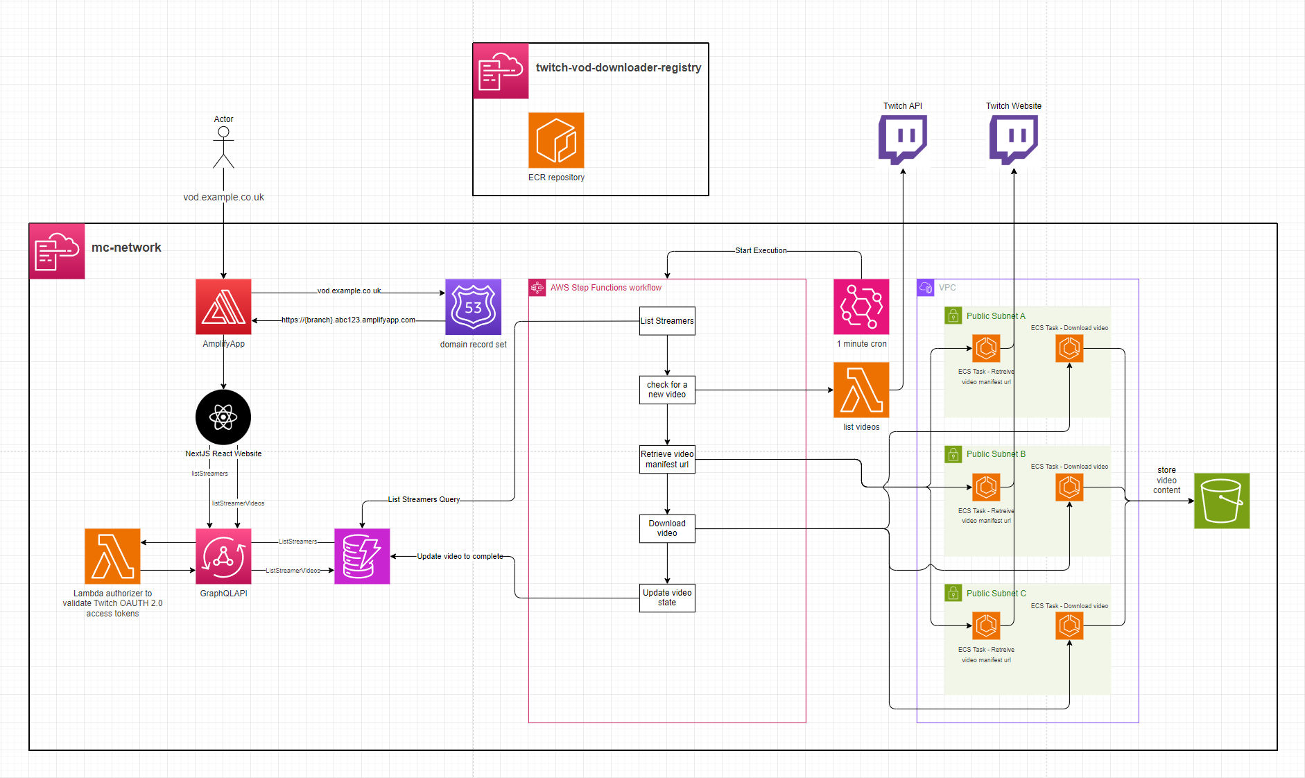
twitch-vod-downloader
Twitch is a livestreaming platform that allows content creators to livestream video to their Twitch channel for people to view and interact with. When a livestream ends, it is then made available as a VOD (Video On Demand) to be watched by people who missed the livestream.
Twitch only allows previous broadcasts to be available for 7 days, or 60 days for their Twitch Partners. After this period, the broadcast is no longer available and, unless downloaded by the streamer, it effectively becomes lost media.
This system is intended to support the automatic archival of content creators' livestreams by downloading the VOD asset and enabling rewatching it from a user interface.
Setup
See .gitlab-ci.yml for automated deployment.
- This application supports logging in by deferring to Twitch via OAuth 2.0. Deploying this application will require registering a Twitch Developer App and then creating a
ConfidentialTwitch application. You will need to create an AWS Secrets Manager secret with the format:
{
  "clientId": "{your client id}",
  "clientSecret": "{your client secret}",
  "url": "https://id.twitch.tv/oauth2/token"
}
- Deploy the
container-registry.yamlCloudFormation stack to host the ECR images. E.g.sam deploy --no-fail-on-empty-changeset --template-file container-registry.yaml --stack-name twitch-vod-downloader-registry --s3-bucket $S3_DEPLOY --capabilities CAPABILITY_NAMED_IAM --region eu-west-1 - Build the
ManifestandDownloadVideodocker images and push them to the ECR repository from step 2. The image tags should beManifestandDownloadVideoto match what the ECS task definitions intemplate.yamlexpect. - Deploy the
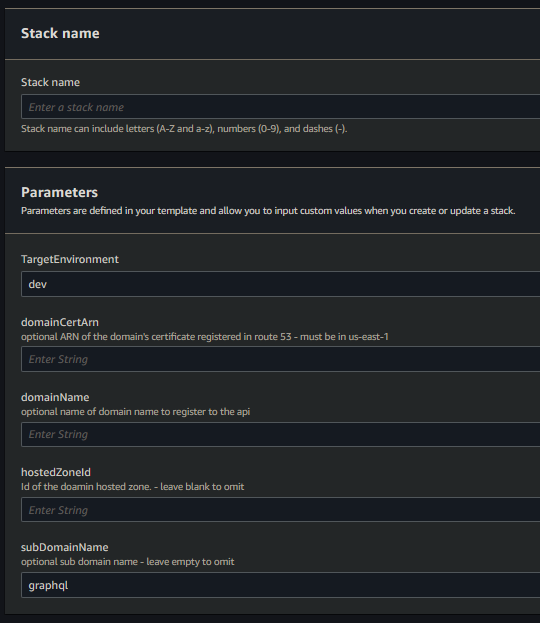
template.yamlwith aDomain,HostedZoneId,DomainCert& optionallyDomainPrefixfor Amplify to be configured with a Route53 domain. TheAmplifyAppRepoURL,AmplifyAppRepoBranch&AmplifyAppRepoTokenParameters need to be provided for Amplify to build the frontend. TheTwitchCredentialsSecretPathparameter needs to be specified, which is the ARN of the Secret created in step 1 and theImageUriparameter will need to be provided as the ECR repository URI for ECS to fetch the docker images.
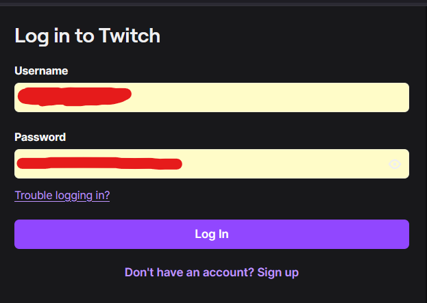
Frontend
The frontend UI integrates with Twitch using an OIDC Cognito Identity Provider. Visiting the frontend redirects you to the Twitch login. After signing in, Twitch redirects you back to the application.
You are then presented with a list of Twitch Streamers that the application is archiving the VODs for.
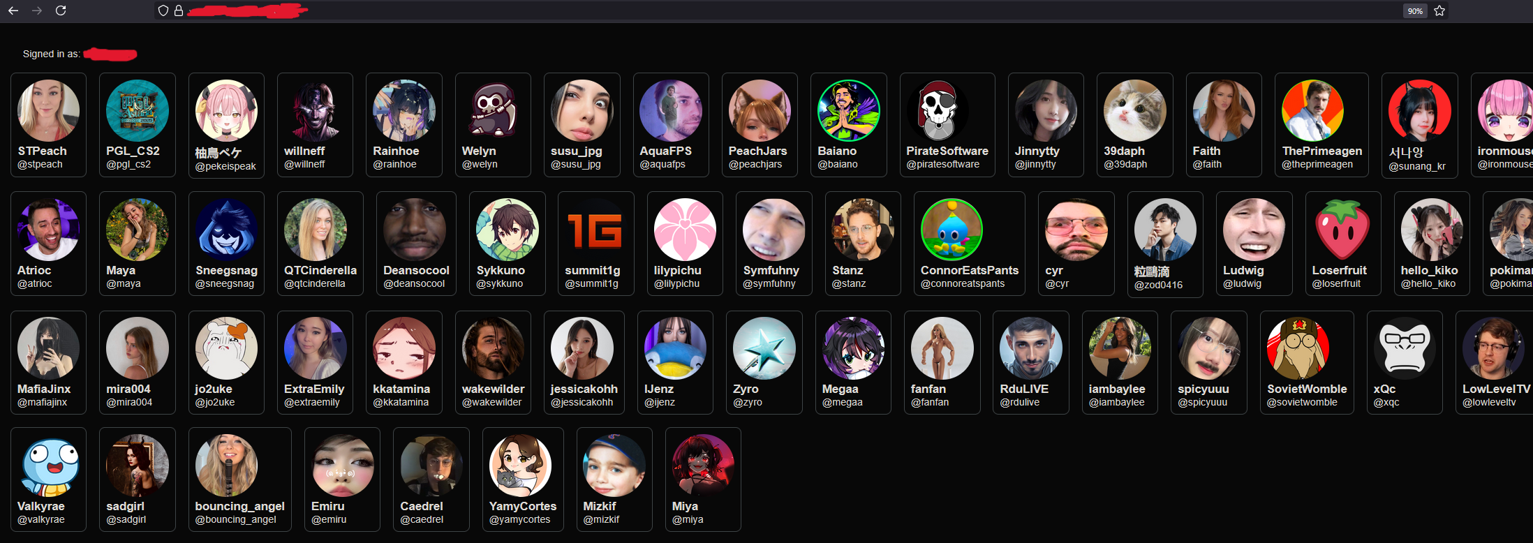
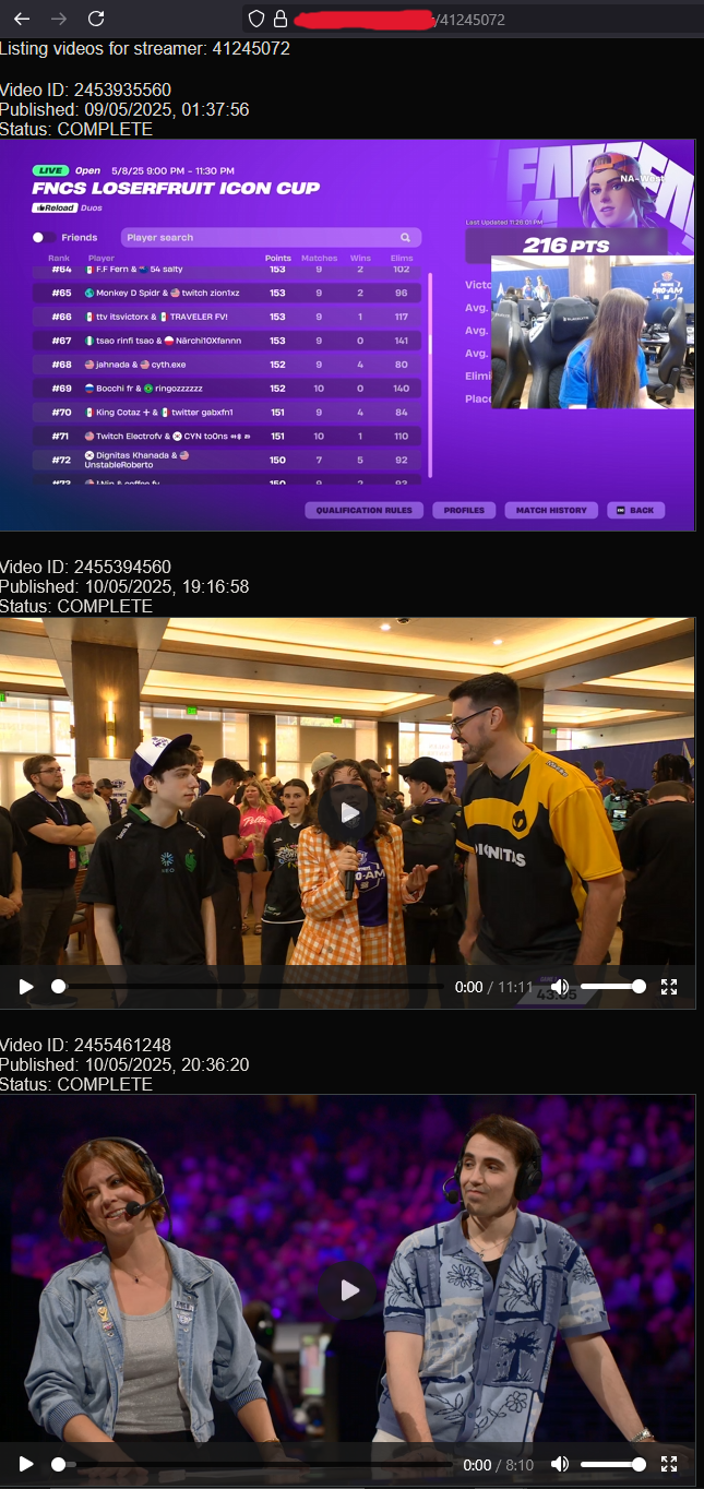
Clicking on a Twitch Streamer will load a list of their videos which have been downloaded and are ready to view.
Registering a Streamer
Registering a new Streamer can be done by making this Appsync mutation
mutation MyMutation {
  createStreamer(username: "pokimane") {
    pk
    sk
    userDisplayName
    userProfileImageUrl
    userName
    userId
  }
}
Dockerized puppeteer webbot
A key piece of this system is taking the url of the Streamer's video and retrieving the HLS manifest url of that video. Twitch's API does not allow this, resulting in a dockerized ECS puppeteer bot which loads the page & intercepts traffic for the HLS manifest url.
Data structures
Streamer
{
 "pk": "STREAMER",
 "sk": "STREAMER#44445592",
 "userDisplayName": "pokimane",
 "userId": "44445592",
 "userName": "pokimane",
 "userProfileImageUrl": "https://static-cdn.jtvnw.net/jtv_user_pictures/912232e8-9e53-4fb7-aac4-14aed07869ca-profile_image-300x300.png"
}
Video
{
 "pk": "VIDEO#44445592",
 "sk": "VIDEO#2458896948",
 "processedManifestUri": "s3://twitch-vod-downloader-video-bucket/44445592/2458896948/index.m3u8",
 "processedManifestUrl": "https://djpcyzz1kzchy.cloudfront.net/44445592/2458896948/index.m3u8",
 "twitchManifestUrl": "https://d2nvs31859zcd8.cloudfront.net/d3c2fadcaee0a608c2d6_pokimane_321069980156_1747261099/chunked/index-dvr.m3u8",
 "twitchVideoUrl": "https://www.twitch.tv/videos/2458896948",
 "userId": "44445592",
 "videoDuration": "11m47s",
 "videoId": "2458896948",
 "videoProcessingStatus": "COMPLETE",
 "videoPublishedTime": "2025-05-14T22:18:25Z"
}
 Order 8:
 Order 9:

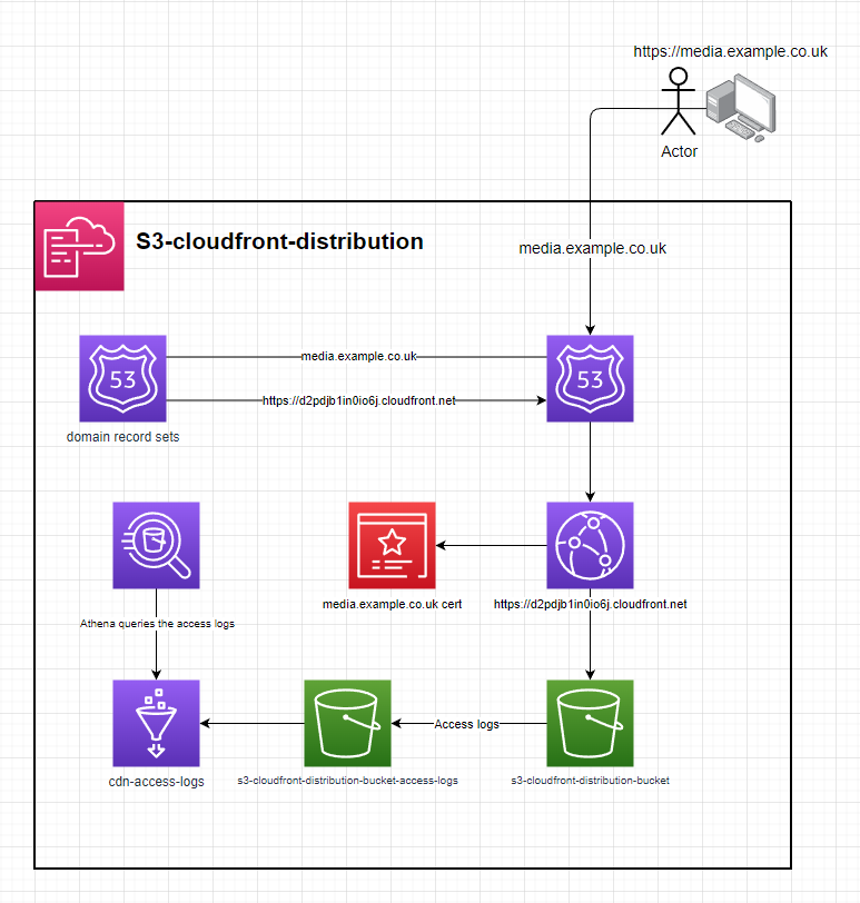
s3-cloudfront-distribution
cloudfront distribution with an s3 origin behind a domain
setup
- deploy the template to cloudformation
- enter the parameters
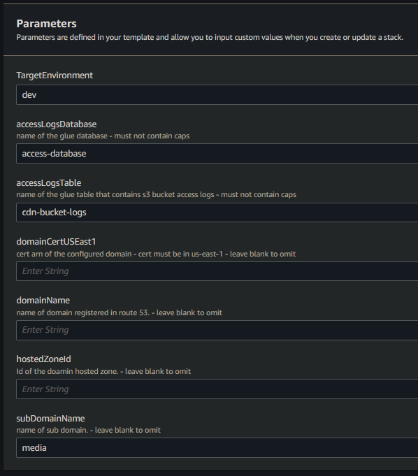
- optionally fill out
domainCertUSEast1,domainName,hostedZoneId&subDomainNamefor cloudformation to configure a CNAME & for route53 to create a recordSet. - upload the contents of /s3 to the origin & it will be accessiable from CloudFront
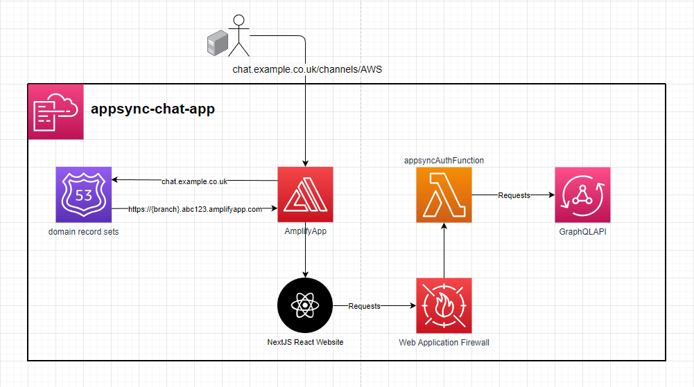
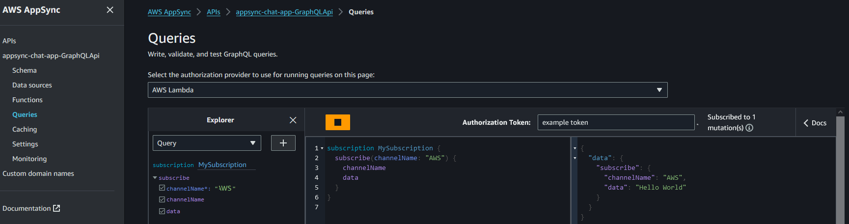
Appsync-Messaging-App
Trying it out
Do you want to see the power of Appsync real-time data? https://chat.matthands.co.uk
Setup
- In order to use Amplify you will need to generate and provide an access token for it to be able to build the frontend. The required scopes are
api,read_api&read_repository - When deploying the stack to AWS, it can optionally be configured with a domain in Route53 via the domain params. WAF can also optionally be setup on the GraphQL API.
- When the stack you will then need to trigger an Amplify job to build the web frontend similar to what's done in the
update-frontendjob in the.gitlab-ci.ymlfile
Usage
From the console
-
Subscribe to receive messages from a channel. E.g.
AWS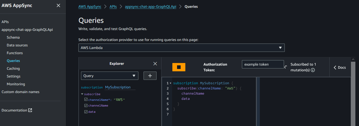
-
Publish a message to that channel
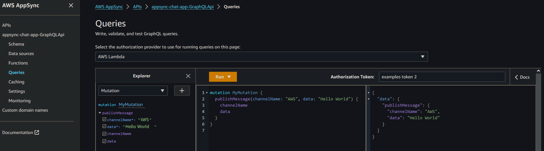
-
Receive that message via the subscription
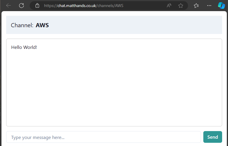
From the Website
- Enter a channel. The website will display a list of example channels but anything following
https://{domain}/channels/{channelName}will work. Entering a channel will subscribe you to receive messages pushed to that channel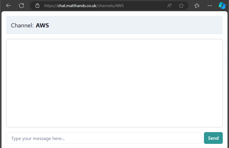
- When any client pushes messages you that channel. all connected clients will receive it over the subscription.
EC2-gitlab-runner-fleet
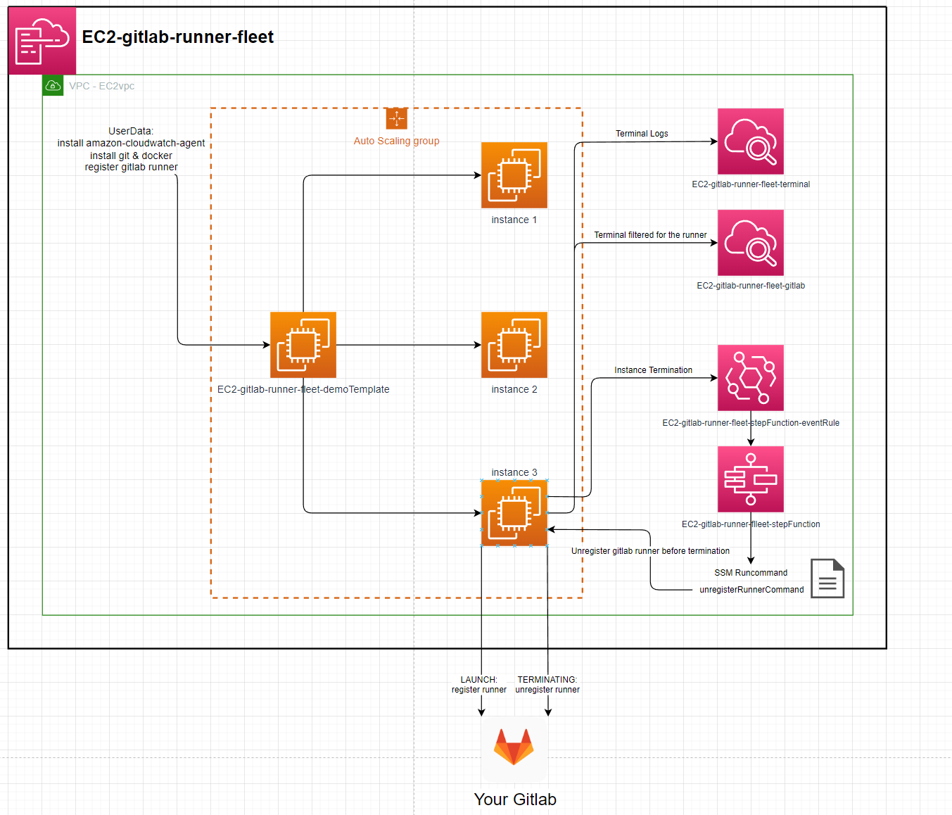
Instance:
- ImageId: ami-084e8c05825742534 (eu-west-2)
- InstanceType: t2.micro
Runners:
- executor: docker
- image: gitlab-runner:latest
- privileged: true (docker-in-docker)
Setup:
- Get Gitlab runner token:
- create a group in your gitlab
- acquire a token for that group: https://gitlab.com/groups/YOUR_GROUP/-/runners
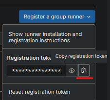
- Download the template.
- Go to AWS Cloudformation, create stack, upload template.
- enter a stack name, your token & a scalingGroupDesiredSize (1 will work).
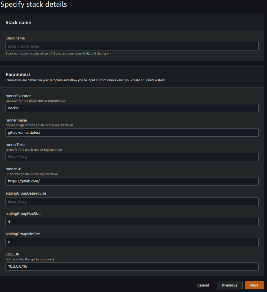
- finish creating the stack.
- the ec2 instances & runners will be created.
- Cloudwatch logs /aws/ec2/STACK_NAME-terminal & /aws/ec2/STACK_NAME-gitlab will show the instances internal logs
- after less than 5 mins the runners will be visible in https://gitlab.com/groups/YOUR_GROUP/-/runners names after the instance they're running on.
Terminating an instance will result in the runner being unregistered before the instance is terminated
EC2 instances backed by EFS
The template in this repository defines an Applicaiton Load Balancer, backed by an Auto Scaling Group that launches public instances across 3 AZ's that mount a shared Elastic File System
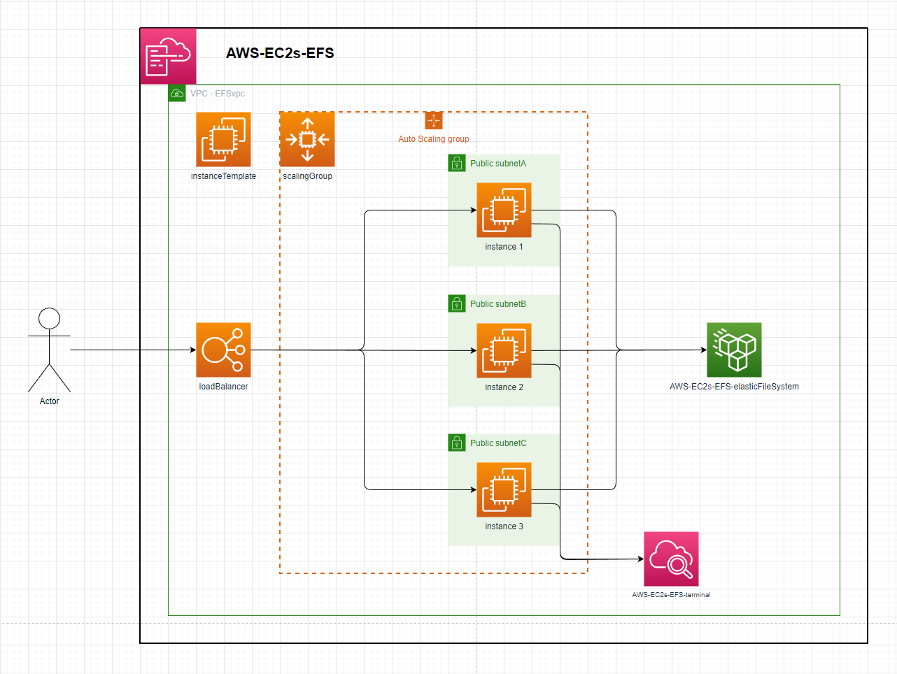
Instance:
- ImageId: ami-084e8c05825742534 (eu-west-2)
- InstanceType: t2.micro
- UserData:
- install & configure amazon-cloudwatch-agent
- install & start httpd
- mount instance to template defined EFS
Setup:
- deploy the template - speficy stack parameters
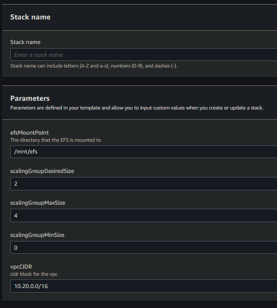
- By default this will create a VPC with the default CIDR parameter. The Auto Scaling Group will launch 2 instances in that VPC behind the Load Balancer. Each instance will mount the EFS to the
efsMountPointdirectory & touch a file into that directory. - After resource creation, each instance will be streaming its terminal logs to cloudwatch. Checking the
efsMountPointdirecotry in any instance will show as many files as there are running instances.
iot-hub-website
Amplify Setup
- In order to use Amplify you will need to generate and provide an access token for it to be able to build the frontend. The required scopes are
api,read_api&read_repository - When deploying the stack to AWS, it can optionally be configured with a domain in Route53 via the domain params.
- When the stack deploys you will then need to trigger an Amplify job to build the web frontend similar to what's done in the
update-frontendjob in the.gitlab-ci.ymlfile
Arduino Setup
-
Find your AWS Account & Region specific
AWS IoT Broker Endpoint- This can be found here: https://console.aws.amazon.com/iot/home#/settings -
create the AWS IoT certificate
aws iot create-keys-and-certificate --set-as-active
The Response will be:
{
  "certificateArn": "arn:aws:iot:{Region}:{AccountId}:cert/2c0f72bf-b230-4c49-9e0e-cbf177926d96",
  "certificateId": "2c0f72bf-b230-4c49-9e0e-cbf177926d96",
  "certificatePem": "-----BEGIN CERTIFICATE-----\n{Certificate}\n-----END CERTIFICATE-----\n",
  "keyPair": {
    "PublicKey": "-----BEGIN PUBLIC KEY-----\n{Public Key Material}\n-----END PUBLIC KEY-----\n",
    "PrivateKey": "-----BEGIN RSA PRIVATE KEY-----\n{Private Key Material}\n-----END RSA PRIVATE KEY-----\n"
  }
}
-
Prepare
arduino_secrets.hfile inarduino/iot-lightbulb/- Enter your Wifi name & password
- Enter your Account & Region specific
AWS IoT Broker Endpointfrom Step 1 - Enter a unique identifier for the device.
- Enter the complete
Device Certificate&Device Private Keyfrom Step 2
-
deploy the
template.yamlincluding thecertificateArnparameter from step 2 -
upload the
.inofile to Arduino using the Arduino IDE -
The board will now listen on the
${DEVICE_ID}/${INCOMING_TOPIC}topic for events targeted for this device
Usage
- Create a cognito user in the userpool
- Associate a device to the user in the
devicesTable
{
 "userId": "${Cognito user sub}",
 "deviceId": "light-bulb",
 "name": "demo light bulb thing",
 "type": "LIGHT_BULB"
}
This associated only allows logged in users to interact with their own devices
Devices before logging in

Login page

Devices after logging in
 The
The On/Off switch for the device will send a message to the arduino over MQTT to turn the LED On or Off.
Arduino setup
When the Arduino receives a message over MQTT it will either be told to turn the LED ON or OFF. The arduino will then set the voltage of the relevant data pin to turn the LED On or Off